
DIY Aeroponic Aframe System Using
PVC Pipe and Containers
System B: V-System
Introduction
In most cases, this system is used to cultivate small plants for the top buds. Seedlings can be induced to flower at 5 weeks while clones can be induced to flower at 6 inches tall.
Plants are grown in a V shape. This allows for a greater yield than plants that are all at the same height. This system can be constructed cheaply with 2×4 wood and 4-inch PVC pipe.
Like most aeroponic systems, this one is used by experienced growers who can easily troubleshoot the system. A novice grower may want to use the NFT V-system on page 121 or the top-feeding V-system on page 86.
The material list below is described for a common 6-pipe system.
Materials:
1. One small mesh per plant (i.e. 31/2 inches).
2. Ten 2x4s to support the 8 to 12-foot lengths of pipe.
3. One 1/8-inch threaded barbed fitting per plant.
4. One-foot piece of 1/8-inch tubing per plant.
5. One reservoir.
6. Six 1/2-inch PVC end caps.
7. Four-inch PVC pipe cut to equal 9 to 10-foot lengths.
8. Twelve 4-inch PVC end caps.
9. 1,200-gallon per hour (or stronger) pump.
10. Bypass valve.
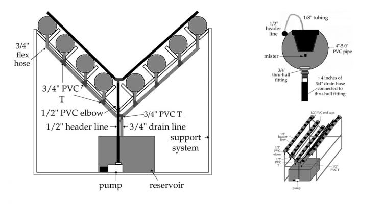
11. 1/2-inch black poly tubing for header lines (75 to 100-foot roll).
11. Two 1/2-inch PVC elbows.
12. Five 3/4-inch PVC Ts.
13. Six 1/2-inch PVC end caps.
14. Six 3/4-inch thru-hull fittings
15. Ten feet of 3/4-inch flex hose.
16. One 11 to 13 PSI mister per plant.
17. Clay or lavarock to fill each pot.
18. 3 to 31/2-inch nails.
Tools
1. Saw.
2. Drill.
3. One-inch holesaw.
4. 3 to 31/2-inch holesaw.
5. Line punch or 1/16-inch drill bit.
6. Hammer.
7. Crescent wrench.
System Construction
Frame
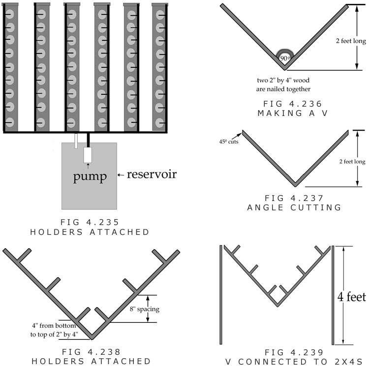
A. Two 3-foot pieces of 2×4 wood are nailed together with 3 to 4-inch nails to make a 90° angle. (Figure 4.236)
B. Both sides should be cut at a 45° angle at 2 feet high.
C. Three 6-inch pieces of 2×4 are nailed to each side of the V-shaped piece of wood.
D. The V is nailed to two 4-foot pieces of 2×4.
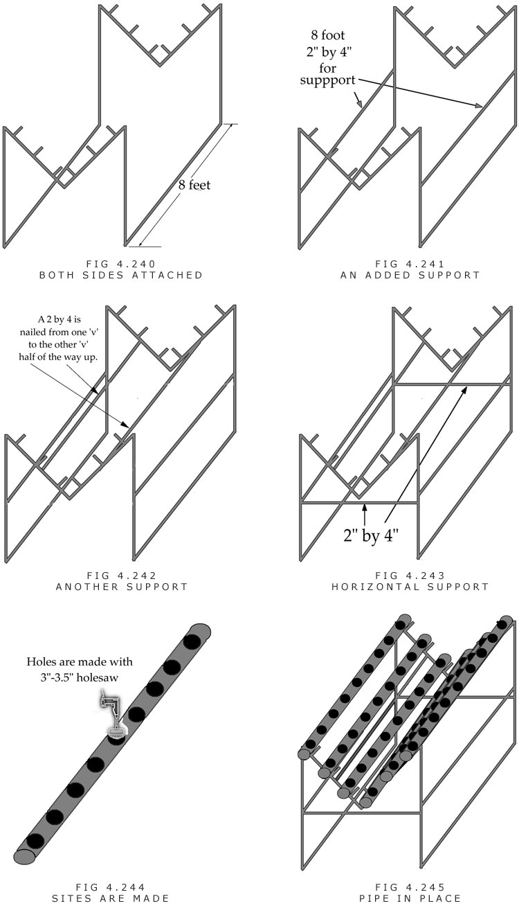
E. The M-shaped pieces are connected together with two 7 to 8-foot pieces of 2×4.
F. The two 7 to 8-foot pieces of 2×4 are nailed halfway up the lengths for additional support.
G. Two 2x4s are nailed from V to V.
H. Two pieces of 2×4 are nailed to the front and back of the frame for extra support.
I. Holes are cut into the pipes at 8 to 10-inch centers. This is 9 to 11 sites per 8-foot piece of pipe.
J. Pipes are placed on stand.
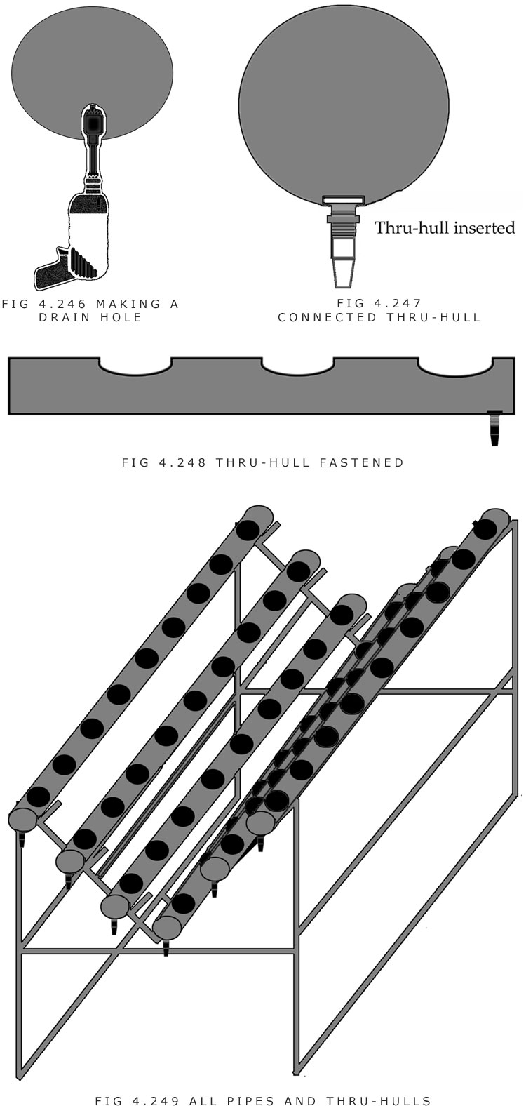
K. A 1-inch holesaw is used to cut holes on the bottom of each pipe for thru-hull fittings. The hole is made in the front.
L. A 3/4-inch thru-hull fitting is inserted into each pipe.
M. 4-inch PVC end caps are connected to both ends of the PVC pipe. PVC glue is used to fasten the end caps.
N. The reservoir is placed under the front.
O. The header line is set up as follows:
1. A piece of 1/2-inch tubing is connected from the pump to a 1/2-inch PVC T.
2. Two pieces of 1/2-inch tubing are connected to the 1/2-inch PVC T. The tubing must reach the highest pipes on each side.
3. 1/2-inch PVC elbows are attached to the ends of the tubing.
4. 1/2-inch PVC Ts are inserted into the tubing next to the other big pipes.
5. 1/2-inch tubing (8 feet) is connected to each 1/2-inch PVC elbow and 1/2-inch PVC T.
6. 1/2-inch PVC end caps are inserted into the ends of all 1/2-inch tubing.
P. The feeder line is set up as follows:
1. A hole is made in the 1/2-inch tubing next to each plant site using a hole punch.
2. A threaded fitting is inserted into each line. 1/8 to 3/16-inch fittings work fine.
3. One-foot of 1/8 to 3/16-inch tubing is cut for each plant site.
4. A hole should be drilled into each 3 to 31/2-inch mesh pot in the middle of the bottom. The hole should be one size smaller than the tubing size to make a tight fit.
5. The 1-foot line is drawn through the hole in the mesh pot. A mister is attached to the tubing.
6. The other end of the 1-foot piece of tubing is attached to the threaded fitting in the 1/2-inch tubing.
7. A pot can be placed securely in each hole. The mister should be an inch or so from the bottom of the pot.
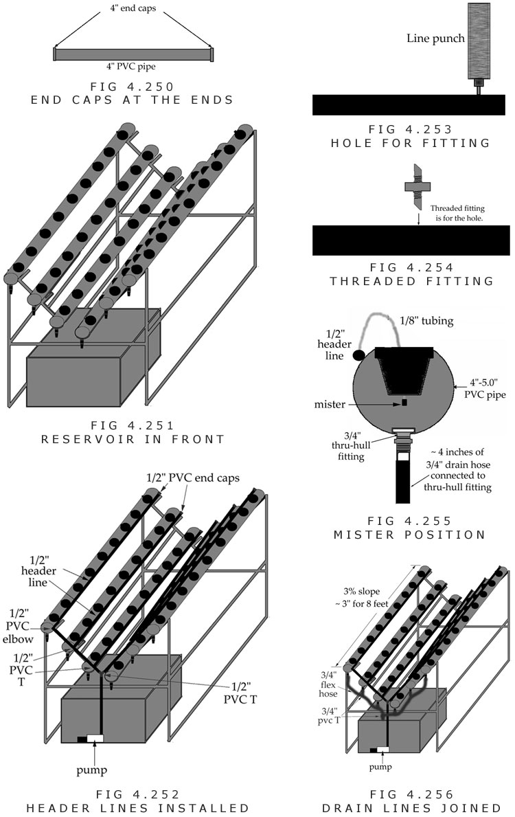
Q. The drain line is set up as follows:
1. The four lowest 3/4-inch thru-hull fittings are connected to 3/4-inch PVC Ts with 6-inch pieces of 3/4-inch flex hose.
2. The highest thru-hull fittings on each side are connected to the nearest 3/4-inch PVC Ts with the flex hose.
3. The lowest and second lowest thru-hull fittings are connected to one another with flex hose.
4. The lowest thru-hulls are connected together with a 3/4-inch PVC T.
5. The loose end of the 3/4-inch PVC T is connected to flex hose that runs inside the reservoir.
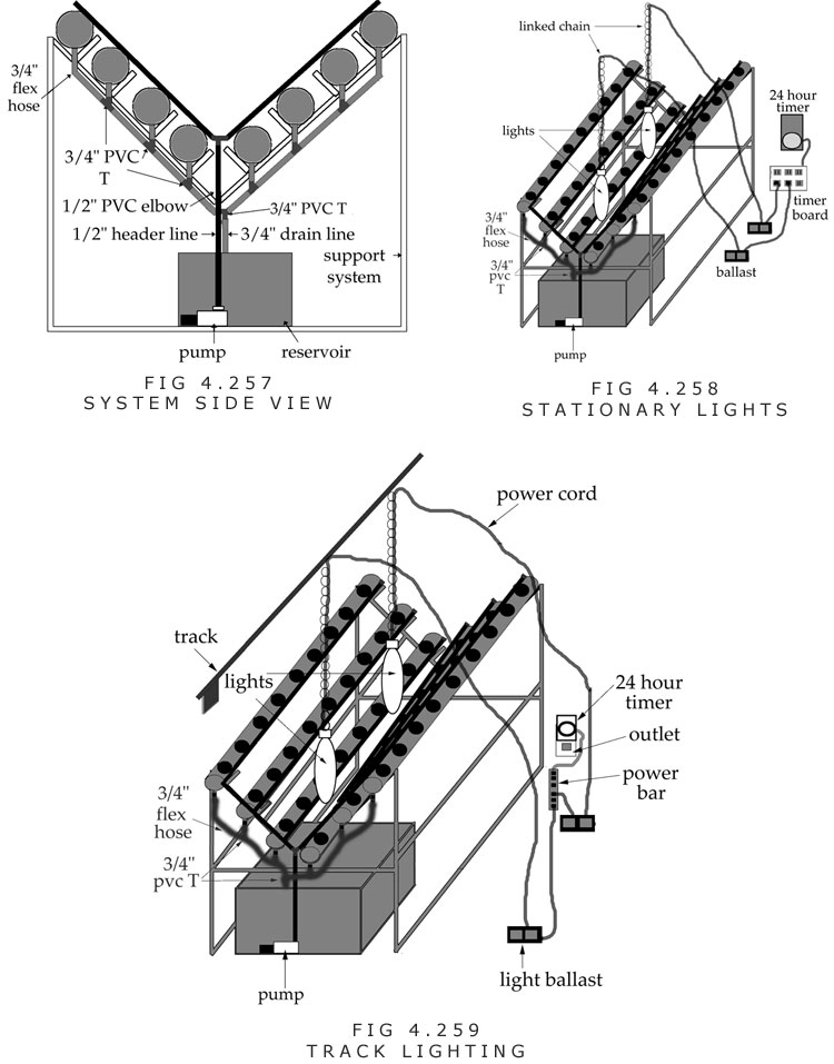
Lighting
R. Two lights can be placed 1/3 the distance from each end. Two 1,000-watt lights would need to run off of a 220 (240)-volt circuit like a dryer or oven or a 30-amp fuse at the breaker box. (Figure 4.258)
A 1,000-watt light and a 400-watt light, or two 600-watt lights could run on a regular household 15-amp circuit.
Track lighting could be used with 2 lights. (Figure 4.259)