
Top-Feeding / Aeroponic System Using PVC Pipe with Containers
Materials
1. One 2-inch mesh per plant, if necessary.
2. One 1/8-inch fitting per plant.
3. One piece of 1/8-inch tubing per plant that is connected from header line to container.
4. One reservoir.
5. Four-inch PVC pipe that is cut to equal lengths that are used to hold the plants.
6. Pump.
7. Bypass valve.
8. 1/2-inch black poly tubing for header lines.
9. 1/2-inch black poly elbows.
10. 1/2-inch black poly Ts.
11. 1/2-inch black poly end caps.
12. 3/4-inch flex hose.
13. One 3-gallon bucket per pipe.
14. 3/4-inch thru-hull fittings.
15. 3/4-inch end cap.
16. 6ml black poly.
17. Twine.
18. Contact cement.
Tools
1. Drill.
2. One-inch hole saw.
3. Exacto knife.
4. Crescent wrench.
5. Custom-sized holesaw (i.e. 31/2-inch) for plant containers, if necessary.
6. Handsaw or skillsaw.
Introduction
In most cases, this system is used to grow small plants. Seedlings can be induced to flower at 5 weeks old, or clones that have reached a height of 6 inches.
Typical uses for this system are 12 pipes at 8-inch centers or 10 pipes at 10-inch centers using three 400-watt lights. Or 28 pipes at 8 i nch centers, or 24 pipes at 10-inch centers using two 1,000-watt lights. But a grower can use half of the pipes described above and double the spacing to grow midsize plants.
This system is a fast, cheap, and easy column system to build. This system will use a medium like soilless mix in the pipe. Soilless mix is the easiest choice.
The feeding in this system can be done continually, or for 2 minutes every 20 minutes.
Procedure
Plant-Holding Components
A. First you’ll need to choose the desired pipe. 4 to 8-inch PVC is a good pipe to use. 4-inch is the cheapest but larger pipe is easier to use because there is more room for the roots. To keep things simple, these instructions are with 4-inch PVC.
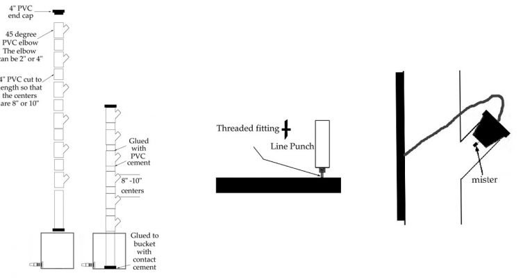
45°, 4-inch PVC elbows are used for the plant holders. (Figure 4.127)
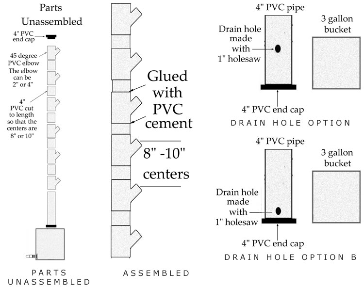
B. All 4-inch piping should be cut into small, 6-inch pieces so that when they are glued with the 45° PVC elbows the distance between plants will be 8 to 10 inches center. (Figure 4.127)
The 4-inch piping is glued with PVC cement to the 4-inch PVC elbows so that the space is 8 to 10 inches center.
C. The tops of the pipes will have 4-inch PVC end caps attached loosely to the top to keep out light. The cap should be able to be removed easily. (Figure 4.127)
 D. One piece of 4-inch PVC should be cut at a height of a few inches to a foot above the buckets. A 4-inch end cap should be glued to the bottom with PVC glue. (Figure 4.128)
E. Option 1:
A hole should be made just below the height of the 3-gallon bucket to drain the solution. (Figure 4.128) The buckets should have a diameter less than the center spacing of 8 to 10 inches.
Option 2:
Pipe is filled with medium like soilless mix. If pipe is filled with medium, the bucket should be placed on 1-foot (or higher) cement blocks to allow for drainage. The drain hole should be just above the end cap. (Figure 4.129)
Drain Components
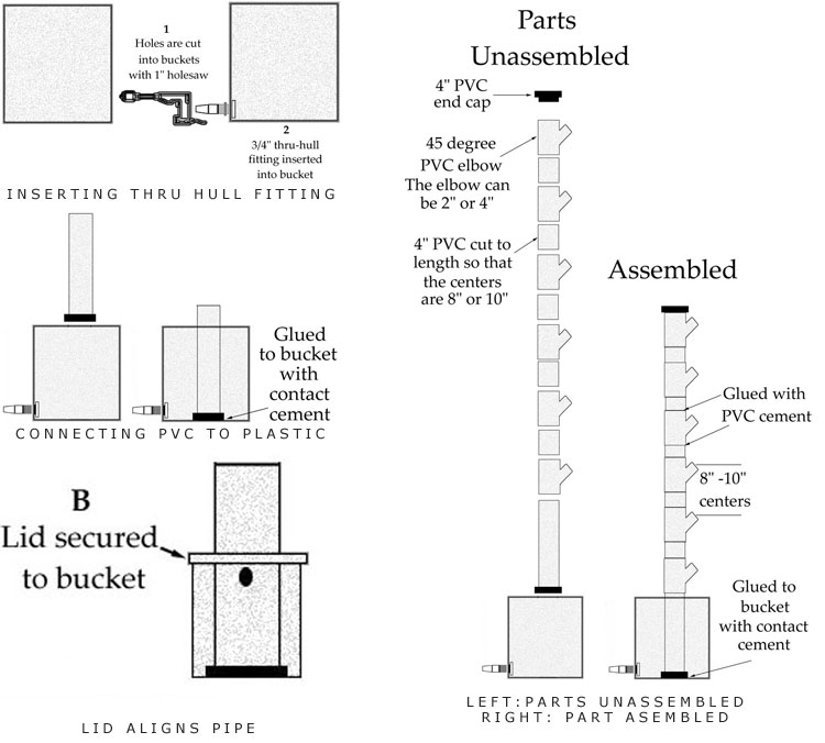
F. Each bucket at the base of the piping should have one hole made about 2 inches from the bottom on each side using a 1-inch holesaw for 3/4-inch thru-hull fittings that will be inserted into each hole. (Figure 4.130)
G. The 4-inch PVC pieces (from step D) can be glued to the bottoms of each bucket with contact cement. The top of each pipe should be at least 1-foot higher than the bucket. The placement in the bucket should be dead center. (Figure 4.131)
H. Each bucket lid should have a hole made into it to fit around the pipe. The lid will add extra support to the pipes and make for less water loss through evaporation. The lid can be placed on the bucket when the glue is dry. Holes can be made with a 4 1/4-inch holesaw, hacksaw, or jigsaw.
I. The columns can be glued with PVC cement to the 4-inch pipe. (Figure 4.133) The columns can be on the same side or opposite side as the thru-hull fittings.
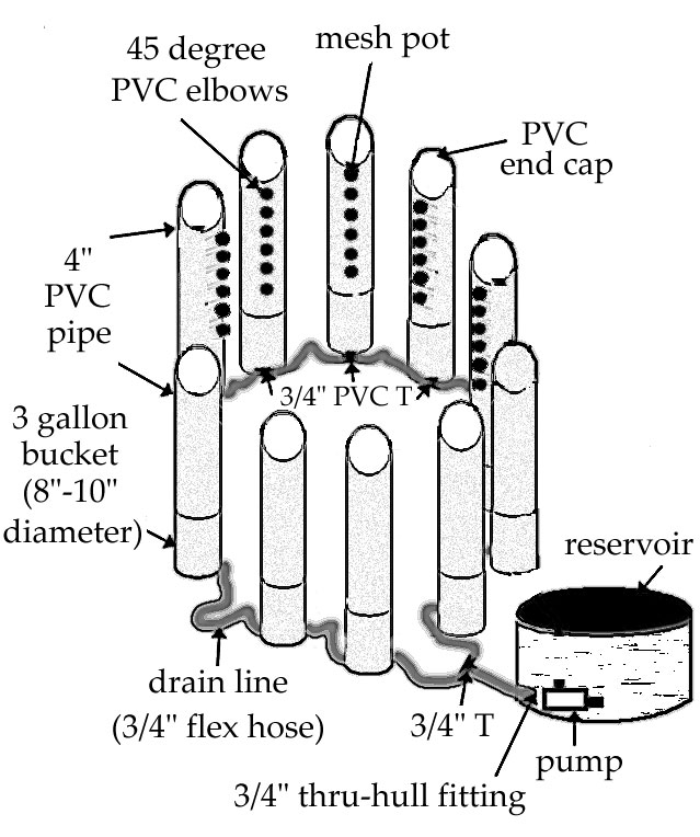
J. The pipes should be placed in a circle to be 1-foot + plant distance from bulbs in middle. (Figure 4.134)
K. 6-inches of 3/4-inch drain hose is attached to each thru-hull fitting. (Figure 4.134)
L. A 3/4-inch PVC T is attached to each piece of 6-inch hose. (Figure 4.134)
M. All drain buckets are connected to each other with tubing that is connected to 3/4-inch thru-hull fittings. (Figure 4.134) This is like a chain that can be shaped any way that is desired in order to place plants at optimum light distances. (Figure 4.134)
N. The first bucket nearest the reservoir will connect to the 3/4-inch thru-hull fitting in the reservoir. (Figure 4.134)
Feeder Line Components
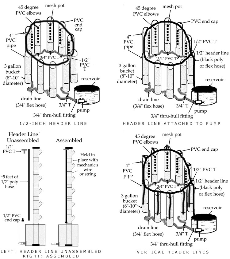
O. 1. A long piece of 1/2-inch poly tubing should run along the tops of the pipes until it reaches the last one in the circle.
2. A 1/2-inch PVC T is inserted at the end. (Figure 4.135)
3. The open end of the 1/2-inch PVC T is connected to a line that runs to the pump at the bottom of the reservoir. A 20-gallon reservoir will do. (Figure 4.136)
4. The main line is cut at each pipe, and a 1/2-inch PVC T is installed for each length of vertical pipe. (Figure 4.137)
 5. The PVC T is connected to pieces of 1/2-inch poly tubing that run down the sides of the large piping to a height just above the top of the reservoir. (Figure 4.138)
6. The poly tubing is connected to 1/2-inch PVC end caps.
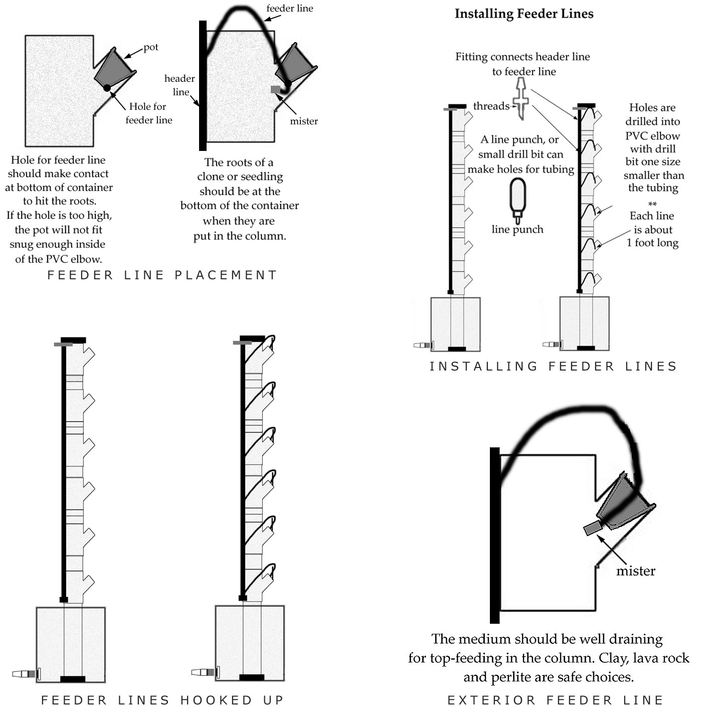
7. Holes are punched and appropriate connection fittings are inserted, such as 1/8-inch fittings for 1/8-inch lines. One fitting is used for each plant.
8. Lines are cut to a length that reaches each plant container with a little slack and inserted into the connection fittings. There are two options. (Figures 4.139 and 4.140 or 4.141 and 4.142)
9. Lines are then connected to alligator stakes.
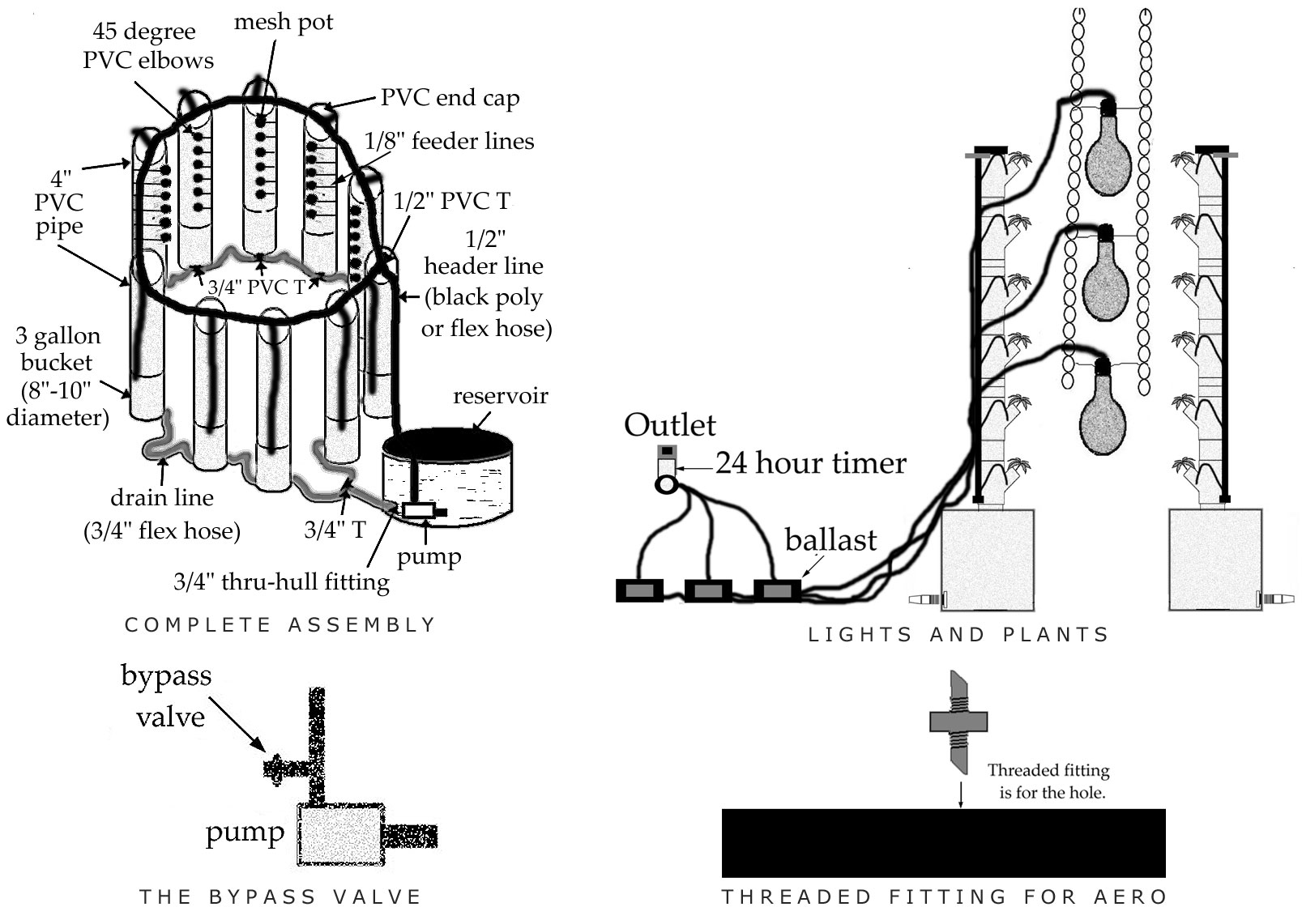
P. The pump is connected to the 1/2-inch poly tubing that reaches the bottom of the reservoir. (Figure 4.143)
Option:
A bypass valve can be inserted be-tween the pump and the first 1/2-inch PVC elbow.
To insert a bypass valve:
1. A 1-inch chunk is cut out of the 1/2-inch poly line.
2. A 1/2-inch PVC T is inserted into the cut out section.
3. A 5-inch chunk of 1/2-inch poly plastic is connected to the 1/2-inch PVC T.
4. A lightweight plastic tap is connected to the 5-inch chunk of 5-inch black poly piece.
Lighting
Q. Lights are hung in between the plants without hoods. For example, three or four 400-watt lights ( 2 to 3 sodiums and 1 halide) can be placed on top of each other to illuminate the plants grown in 6-foot high pipe.
Feeding
R. It is easiest to feed the plants with the pump timer running full-time, only during the light hours. But, plants can be fed continuously (all day and all night). Also, plants can be fed intermittently (i.e. every 20 minutes for 2 minutes, every 2 to 5 minutes for 30 seconds) during all hours.
Detailed feeding options and instructions are provided in chapter 5.
Aeroponic Conversion
Making the aeroponic version of this system is easier than making the top-feeding system.
A. The lines that run down the outsides of the column will be cut from the small feeder lines and disconnected from the 1/2-inch PVC Ts and removed from the 1/2-inch PVC T. (Figure 4.141)
B. A new piece of identically sized 1/2-inch hose is cut.
C. The 1/2-inch end cap from the old tubing is put in one end of the new tubing.
D. The new 1/2-inch tubing is reconnected to the PVC T and is connected to the feeder tubing with threaded fittings. (Figure 4.146)
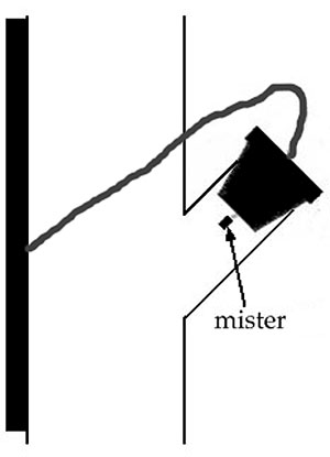
E. An 11 to 13 PSI mister is inserted into the end of the feeder line, then placed in position. (Figure 4.147)
F. The pump should be changed to a high-pressure pump designed for aeroponics. The pump should be the size required for the garden dimensions. A 1,200-gallon per hour pump will work with 11 to 13 PSI misters. High-pressure pumps are available at hydroponic stores, water supply places, and on the Internet.