
DIY Top Feeding Hydroponic V-System
Using PVC Pipe
Introduction
This system uses two lights and six 4 to 5-inch PVC pipes to grow small plants. 4-inch PVC is the cheapest option.
Rooted clones or 4 to 5-week-old seedlings can be induced to flower to grow plants that will be 14 to 18 inches at maturity.
The pipes are placed in V position. This system can produce more volume per square foot than the flat PVC pipe system.
A novice grower could place a medium on the bottom of each pipe for the roots.
Materials
All materials and step-by-step construction for this system will be given on the next pages.
Tools
1. Saw.
2. Drill.
3. 3 to 31/2-inch holesaw.
4. Line punch or 1/16-inch drill bit.
5. Exacto knife or sharp knife.
6. One-inch holesaw.
7. Hammer.
8. Crescent wrench.
Construction
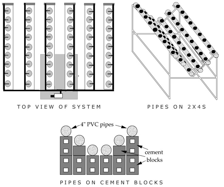
The PVC pipes can be placed on a support system made with 2x4s or cement blocks. The support system is lighter. The instructions for the building of this system use the 2×4 frame, but if the construction is done with cement blocks, the setup remains the same.
Frame
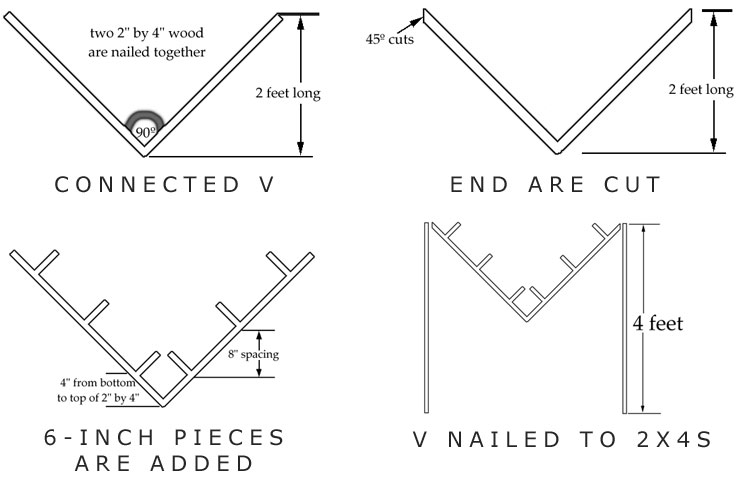
A. Two 3-foot pieces of 2×4 wood are nailed together with 3 to 4-inch nails to make a 90° angle. (Figure 4.98)
B. Both sides should be cut at a 45° angle at 2 feet high. (Figure 4.99)
C. Three 6-inch pieces of 2×4 are nailed to each side of the V-shaped piece of wood. (Figure 4.100)
D. The V is nailed to two 4-foot pieces of 2×4. (Figure 4.101)
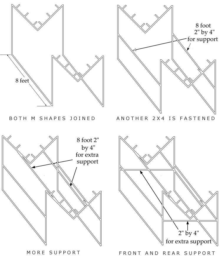
E. The M-shaped pieces are connected together with two 7 to 8-foot pieces of 2×4.
F. Two 7 to 8-foot pieces of 2×4 are nailed halfway up the lengths for additional support.
G. Two 2x4s are nailed from V to V.
H. Two pieces of 2×4 are nailed to the front and back of the frame for extra support.
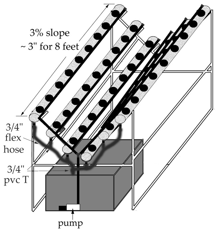
I. Holes are cut into the pipes at 8 to 10-inch centers. This is 9 to 11 sites per 8-foot piece of pipe.
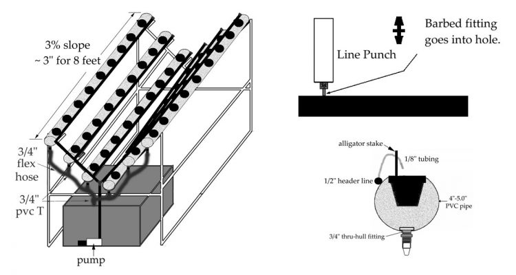
J. Pipes are placed on stand.
K. A 1-inch holesaw is used to cut holes on the bottom of each pipe for thru-hull fittings. The hole is made in the front.
L. A reservoir goes under the system. (Figure 4.111)
M. A 3/4-inch thru-hull fitting is inserted into each pipe.
N. 4-inch PVC end caps are connected to both ends of the PVC pipe. PVC glue is used to fasten the end caps.
O. The header line is set up. (Figure 4.111)
1. A piece of 1/2-inch tubing is connected from the pump to a 1/2-inch PVC T.
2. Two pieces of 1/2-inch tubing are connected to the 1/2-inch PVC T. The tubing must reach the highest pipes on each side.
3. 1/2-inch PVC elbows are attached to the ends of the tubing.
4. 1/2-inch PVC Ts are inserted into the tubing next to the other big pipes.
5. 1/2-inch tubing (8 feet) is connected to each 1/2-inch PVC elbow and 1/2-inch PVC T.
6. 1/2-inch PVC end caps are inserted into the end of all 1/2-inch tubing.
P. The feeder line is set up.
1. A hole is made in the 1/2-inch tubing next to each plant site using a hole punch.
2. A barbed fitting is inserted into each line. 1/8 to 3/16-inch fittings work fine.
3. One-foot of 1/8 to 3/16-inch tubing is cut for each plant site.
4. Plants can be transplanted into a medium such as clay or lava rock. Hydroton clay pellets are a popular choice. The pots with plants can be placed securely in each hole.
5. An alligator stake should be placed into each 3 to 31/2-inch mesh pot.
6. The one-foot line is drawn through the hole in the alligator stake so that the solution will pour into the pot.
7. The other end of the 1-foot piece of tubing is attached to the fitting in the 1/2-inch tubing.
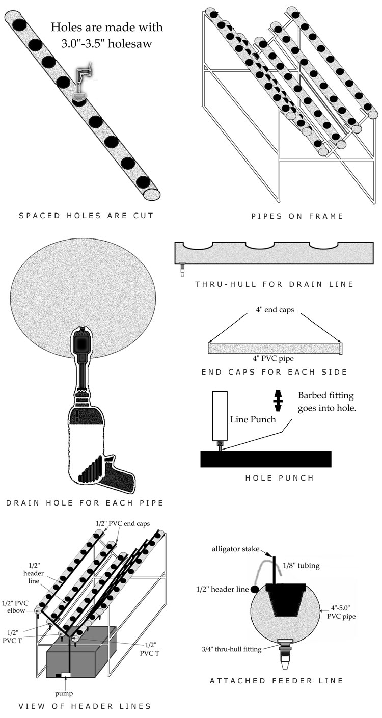
Q. The drain line is set up. (Figure 4.114)
1. The four lowest 3/4-inch thru-hull fittings are connected to 3/4-inch PVC s with 6-inch pieces of 3/4-inch flex hose.
2. The highest thru-hull fittings on each side are connected to the nearest 3/4-inch PVC Ts with the flex hose.
3. The lowest and second-lowest thru-hull fittings are connected to one another with flex hose.
4. The lowest thru-hulls are connected together with a 3/4-inch PVC T.
5. The loose end of the 3/4-inch PVC T is connected to flex hose that runs inside the reservoir.
Lighting
P. Two lights can be placed 1/3 the distance from each end.
Two 1,000-watt lights would need to run off of a 240-volt circuit like a dryer or oven or a 30-amp fuse at the breaker box.
A 1,000-watt light and a 400-watt light, or two 600-watt lights could run on a regular 15-amp household circuit.
Track lighting could be used with 2 lights. (Figure 4.116)
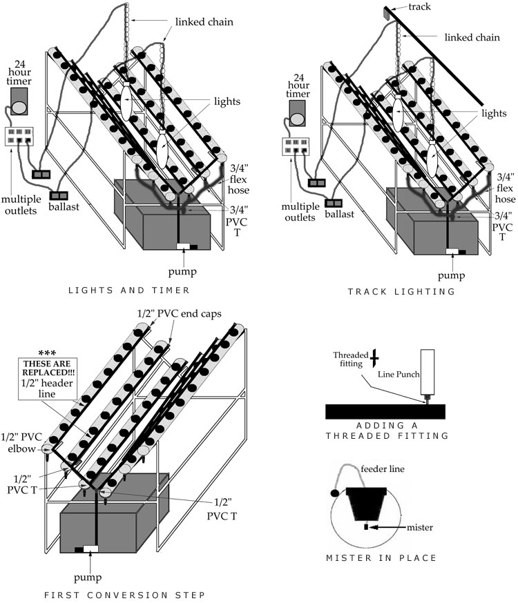
Aeroponic Conversion
A. Each feeder line (3/16-inch) that is connected to a pot is removed.
B. The 1/2-inch lines that run down the outsides of the 4-inch PVC pipes are disconnected from the 1/2-inch PVC Ts and elbows. (Figure 4.117)
C. New 1/2-inch lines replace the old ones.
The setup is identical to the top-feeding construction on page 66 except for the slight differences listed below.
1. A threaded fitting is used to connect the feeder tubing to the 1/2-inch lines.
2. The small feeder line runs through the pot. (Figure 4.119)
3. An 11 to 13-PSI mister is inserted into the end of the feeder line. (Figure 4.119)
4. The pump should be changed to a high-pressure pump designed for aeroponics. The pump should be the size required for the garden dimensions. A 1,200-gallon per hour pump will work with 11 to 13-PSI misters.