
This is vertical gardening using grow sacks. It is the cheapest vertical garden option available. It will take on a farm look. Don’t expect it to raise property value and be eye popping unless plants are covering it up.
Vertical Grow Bag Garden
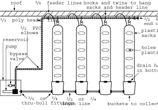
Option E: Column System #2
Top-Feeding Using Plastic Sacks
Tools
1. Exacto knife.
2. Crescent wrench.
Materials
1. One reservoir for feeding.
2. One reservoir for flushing.
3. Plastic horticulture sacks
4. Pump.
5. Bypass valve.
6. 1/2-inch black poly tubing for header lines, 1/8-inch poly for feeder lines.
7. 1/2-inch black poly elbows.
8. 1/2-inch black poly Ts.
9. 1/2-inch black poly end caps.
10. 3/4-inch flex hose.
11. One bucket per pipe to collect runoff solution.
12. 3/4-inch thru-hull fittings.
13. 3/4-inch end cap.
14. Twine.
Plant-Holding Components
A. Plastic horticulture sacks are filled up with medium (i.e. soilless mix). Bigger sacks give more area for vegetation to cover.
B. All sacks should be hung from a sturdy beam. For easy maintenance, the height should be less than the length of an outstretched arm so that a grower does not need to use a ladder while building the system.
The sacks should be placed in the desired locations, such as rows.
C. Small drain holes should be inserted into the bottoms of the sacks.
Drain Components
D. The buckets (or boxes) at the base of the sacks should have holes made about 2 inches from the bottom on each side using a 1-inch hole saw. 3/4-inch thru-hull fittings are then inserted into each hole. Square plastic boxes, plastic buckets, or plywood boxes with two layers of black poly can be used. If plywood is used, care must be used when the thru-hull fittings are inserted because any rips will trap water under the plastic, which can lead to the solution overflowing.
E. The sacks should drain into the buckets without making a mess.
F. The reservoir should have a hole about 2 inches from the bottom that is made with a 1-inch hole saw. A 3/4-inch thru-hull fitting is inserted into the hole; the end of the 3/4-inch thru-hull fitting will be attached to the T-fitting from the drain line of the first bucket (or box) with 1/2-inch poly tubing (or 3/4-inch flex hose).
G. Each row will have a T-fitting inserted at the end of the drain line that is nearest the reservoir. If 3/4-inch flex hose is used, a 3/4-inch PVC T will be used. For 1/2-inch tubing, 1/2-inch or 3/4-inch fittings can be used for all drain parts. 1/2-inch black poly is the cheapest option, but 3/4-inch flex hose is the superior product. The last row will be have a 5-inch piece of tubing connected to the loose end of the PVC T, followed by an end cap. Using a PVC T is a good idea if more rows may be connected later.
H. The sacks are soaked until the medium is saturated. Then, they can be refilled and remoistened if necessary.
I. Holes are cut in the sacks for the plants with the exacto knife. It is recommended that you know what area a plant will cover until harvest so that the holes can be made in precise locations. It may take a crop or two to figure this one out.
Feeder Line Components
J. 1. A long piece of 1/2-inch poly tubing should be run along the support beam so that it reaches near all of the sack tops. Twine and screw-in hooks can be used to keep it in position. An end cap should be inserted at the end.
2. The front of the 1/2-inch poly tubing should have a 1/2-inch PVC elbow or PVC T inserted into it. A PVC T is used instead of the PVC elbow if more than one row is used.
3. The small 1/8-inch poly tubing is then connected to the 1/2-inch main line with the appropriate connection fittings that connect to the individual feeder lines. A hole punch is used to make the hole for the connectors.
4. Lines are cut to a length that reaches the top of each sack. Only one line per sack is used.
5. Lines are then connected to alligator stakes.
K. The pump is connected to a piece of poly tubing that reaches the outside of the reservoir.
Option: A bypass valve can be inserted between the pump and the first 1/2-inch PVC elbow. To insert a bypass valve, a 1-inch chunk is cut out of the 1/2-inch poly line, a 1/2-inch PVC T is inserted, a 5-inch chunk of 1/2-inch poly plastic is connected to the PVC T, and a lightweight plastic tap is attached to the 5-inch chunk of 5-inch black poly.
L. The end of the line from the pump is connected to a 1/2-inch PVC elbow.
M. The 1/2-inch PVC elbow is connected to a piece of 1/2-inch poly tubing that reaches the tubing that hangs down from the front of the first sack.
N. A 1/2-inch PVC elbow is used to connect the lines that run along the roof beam to the tubing running from the pump.
Feeding
Plants can be fed continually or intermittently with the pump running on a timer. Continually can be full-time, or only during light hours. A solar pump would run in the light hours without a timer.
Intermittently means a timer can run the pump every 20 minutes (for a few minutes), or every 2 days for a few hours or so. Plants will grow fine as long as the medium does not dry up. Feeding every few days is the easiest way, but growth will be slower than plants fed with continual feeding.
Drain to Waste Conversion
The entire drain system mentioned in steps 4 to 7 can be eliminated. If this is the case, it is recommended that you feed so that everything stays saturated, yet the runoff through the drain holes in the plastic sacks is minimal.
NFT (Nutrient Film Technique)
With nutrient film technique, plants can be fed with continuous or intermittent film that is pumped through a header line, then drained down a trough, PVC pipe, or flood table. The solution travels down the bottom of the trough where it collects in the reservoir, before it is recirculated. The solution can run all day.
Capillary matting can be placed under trough.
Air pumps can be used to aerate the nutrient solution.
Automatic thermostatic heat cords can be placed around a reservoir to keep the solution warm. Chillers cool the reservoir.
The only difference in building this system from the top-feeding system on pages 29 to 33 is the header line. The 1/2-inch poly or PVC header line runs along the side, then it connects to a matching elbow. Then it runs along the back of the pipes until it reaches the end. The header line is end-capped at the end. Only one feeder line is connected to the header line on each each pipe to deliver the solution down the pipe.